Have Additional Questions? Contact Us →

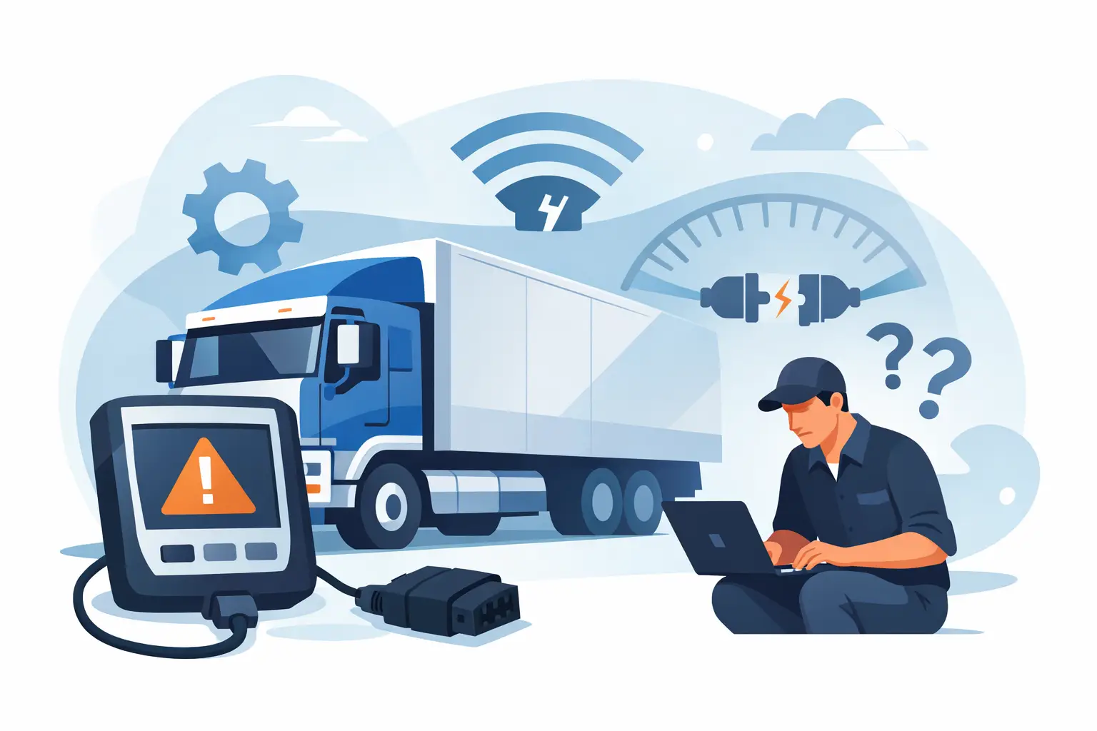
A diagnostic job can stop before it starts when the VCI will not establish communication. If you are asking why your lorry diagnostic interface is not connecting, do not assume the interface has failed. On a commercial vehicle, the fault can sit in the lorry power supply, diagnostic socket, CAN network, cable, software configuration or vehicle access conditions. Replacing hardware before checking these basics costs time and can leave the original fault untouched.
Why Is Your Lorry Diagnostic Interface Not Connecting?
A diagnostic interface needs three things at the same time: stable power, a physical data path and the correct communication protocol. A break in any one of them can produce the same message on screen: no communication with vehicle.
This is why generic fault-finding often wastes workshop time. A tool may power up correctly from USB but receive no ignition voltage at the vehicle socket. It may detect the interface on the laptop but be set to the wrong manufacturer connection type. Or it may connect to the engine ECU while failing to reach the SCR, EBS or body control system because a separate CAN branch has a fault.
Start by separating the problem into two questions. Does the computer recognise the diagnostic interface? Then, does the interface communicate with the vehicle? The answer tells you whether to focus on the laptop and software, the VCI and cable, or the lorry itself.
Check Power at the Diagnostic Socket First
A lit interface is not proof that the vehicle-side connection is correct. Some units are powered by the computer, while the vehicle diagnostic port still lacks battery supply, ignition supply or a proper earth. Use a multimeter at the relevant pins rather than relying on an LED.
Most heavy-duty applications use either a 9-pin Deutsch connection or a 16-pin OBD-style connector, but pin assignments and adapter requirements vary by vehicle, year and system. A DAF, MAN, Iveco, Mercedes-Benz, Scania, Renault or Volvo may have different workshop connection arrangements depending on its generation. The connector can also be physically intact while a terminal is spread, corroded or pushed back into the housing.
Check for battery voltage, switched ignition where required, and a low-resistance earth. If supply voltage falls sharply when the ignition is switched on, investigate battery condition, fuses, relays and shared earth points. Low voltage is especially common after a vehicle has stood for a period or where auxiliary equipment has drained the batteries.
Do not overlook the obvious workshop issue: the wrong lead. A 16-pin adapter may fit a socket yet not carry the pins required by the selected VCI or vehicle protocol. Use the cable specified for the diagnostic platform and vehicle range, not simply one that looks compatible.
Confirm the Interface, Driver and Software Setup
If the lorry socket has correct supply and earth, move to the computer side. Connect the interface to the laptop without the vehicle attached. The operating system should show the VCI consistently, whether it uses USB, Bluetooth, Wi-Fi or Ethernet. An intermittent connection at this point points to a damaged USB lead, poor port, insufficient laptop power, driver issue or interface fault.
Workshop software must also be configured for the correct device. Many platforms require a selected VCI type, communication port or network address before a vehicle scan can begin. After a software update, these settings can revert. A diagnostic suite may open normally but have no active interface assigned.
Driver and firmware versions matter. Older interfaces may not work correctly with a newer operating system or diagnostic release, while an interrupted firmware update can leave a VCI visible to the PC but unable to communicate with a vehicle. Follow the tool supplier’s update procedure and avoid updating through an unstable wireless connection.
Licensing is another practical check. Some manufacturer-level applications allow the software to launch but limit access when the licence, subscription or security token is not active. This is not the same as a wiring fault, but it can be reported as a connection or authorisation error. Read the exact message before dismantling anything.
Match the Correct Protocol to the Vehicle
Commercial vehicle diagnostics are not one protocol across every module. J1939 CAN is common on heavy vehicles, but older systems may use J1708 or manufacturer-specific arrangements. Even on a modern EURO 5 or EURO 6 lorry, engine, transmission, SCR/AdBlue, braking and body systems can have different access conditions.
Select the exact make, model, model year and system where the software requests it. Automatic identification is useful, but it depends on communication already being available. If auto-scan fails, enter the vehicle details manually and try the correct system route.
A generic code reader may access emissions-related OBD data yet not communicate with the full manufacturer network. That does not prove the lorry is faulty. It may simply be a capability limit of the tool. For coding, programming, calibration or detailed SCR diagnosis, use hardware and software designed for that vehicle family and function.
There is also a trade-off with universal interfaces. They offer useful coverage for mixed fleets, but full access can require brand-specific software, an approved VCI mode or an additional adapter. Confirm compatibility before diagnosing a no-connection complaint, particularly on newer vehicles with protected gateways.
Check Ignition State and Vehicle Security Access
Many ECUs will not wake up fully with the key removed. Switch the ignition on and allow the dashboard network to initialise before connecting. On some vehicles, diagnostic access is more reliable with the engine stopped, auxiliary consumers off and battery support connected if programming is planned.
Newer lorries can use secure gateway functions that restrict diagnostic sessions. In this case, the interface may connect to the vehicle but be blocked from reading or writing selected control units. The remedy is authorised access through the appropriate software process, not repeated cable swapping.
Aftermarket immobilisers, telematics systems, tracker installations and non-standard bodybuilder wiring can also affect network behaviour. If communication failed after an accessory installation or electrical repair, inspect that work first. A pinched CAN pair, poor splice or incorrectly fitted module can disrupt more than one ECU.
Test the CAN Network Before Condemning the Tool
When power, cable and software checks are correct but every system remains unavailable, test the vehicle network. A proper CAN diagnosis should include voltage checks and resistance testing with the vehicle powered down and the correct procedure followed. A healthy high-speed CAN network normally shows approximately 60 ohms across CAN high and CAN low when measured at the appropriate point with the network asleep.
A reading near 120 ohms can indicate a missing termination or an open circuit. A very low reading may suggest a short or an additional termination. Values alone are not a final diagnosis, as network layouts vary, but they quickly show whether further wiring investigation is justified.
Where only one ECU will not communicate, check its feeds, grounds, connectors and local CAN branch before testing the whole vehicle. For example, if engine and EBS systems respond but the SCR control unit does not, the fault may be local to the emissions system rather than the main diagnostic socket. Water ingress around chassis-mounted components and harness sections deserves particular attention.
A Fast Workshop Test Order
Use a fixed process rather than changing parts at random:
- Verify battery condition, socket power, ignition feed and earth.
- Confirm the correct VCI, lead and adapter for the vehicle.
- Check that the laptop detects the interface and that the selected driver is stable.
- Confirm software version, licence status, VCI assignment and vehicle selection.
- Test communication with another known-good vehicle, then test the suspect lorry with a known-good interface if available.
- Investigate CAN wiring, ECU supplies and secure gateway access only after the connection equipment has been proven.
Testing against a known-good vehicle is one of the quickest ways to protect workshop time. If the same interface and laptop communicate immediately with another compatible lorry, the fault is likely vehicle-side. If neither vehicle connects, return to the VCI, cable, driver and software setup.
When Replacement Is the Right Call
Replace the interface or cable only when the evidence supports it. Physical damage, overheated connectors, unreliable USB detection, repeated firmware faults or confirmed failure on multiple compatible vehicles are strong reasons. A cable is often the cheaper and more vulnerable part, so inspect and test it before condemning the VCI.
For workshops handling several makes, keep proven leads and an alternative compatible interface available. This is not duplication for its own sake. It is a practical way to distinguish a vehicle fault from a diagnostic equipment fault while a revenue-generating bay is occupied.
A no-connection message is a starting point, not a diagnosis. Work from socket supply and correct cable selection through to software configuration and network testing, and the fault normally becomes clear before unnecessary hardware is ordered.
