Have Additional Questions? Contact Us →

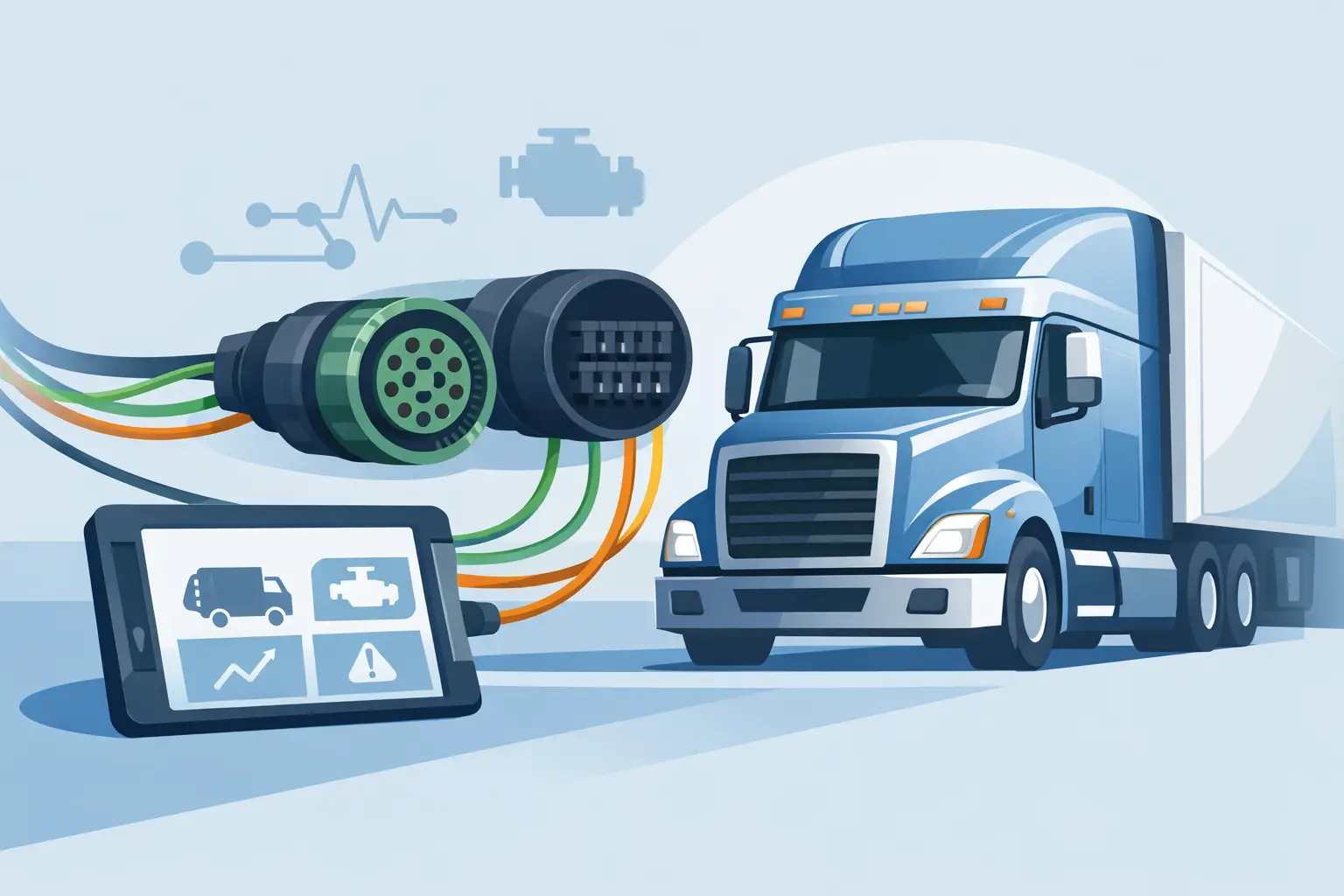
A lorry can show a dozen unrelated fault codes when the real problem is one damaged CAN pair, a corroded connector or an incorrect termination point. This J1939 wiring guide is written for workshop technicians who need to establish whether the network is healthy before condemning an ECU, sensor, instrument cluster or aftertreatment component.
J1939 is the communication standard behind many heavy-duty vehicle systems. It allows engine management, transmission, ABS/EBS, body electronics, dashboard, retarder and emissions control modules to exchange data on a shared CAN network. When that network is interrupted, the symptoms can range from a no-start condition to derate, missing gauges, inactive diagnostics or multiple modules that cannot be identified by a scan tool.
Understand the J1939 wiring layout first
A J1939 network is normally built as a backbone with short branch connections, often called stubs, leading to individual control units. The backbone uses a twisted pair: CAN High and CAN Low. Twisting is not cosmetic. It helps reject electrical interference from alternators, injectors, motors and other high-current systems common on commercial vehicles.
On a typical 250 kbit/s J1939 network, the two CAN wires are commonly colour-coded yellow and green. However, wire colours are not a diagnostic standard. A DAF, MAN, Volvo, Scania, Renault, Iveco or Mercedes-Benz vehicle may use different colours, connector locations and network arrangements according to model year and equipment level. Always identify the circuit from the correct vehicle wiring diagram and connector pinout.
The network also requires two 120-ohm terminating resistors, one at each physical end of the backbone. These resistors control signal reflection. With both fitted and the circuit intact, a resistance check measured between CAN High and CAN Low should normally read approximately 60 ohms.
That single reading is useful, but it is not a full verdict on network condition. A correct 60-ohm reading does not prove that every module, branch wire and connector is working under load. Equally, an abnormal reading can be caused by a module still awake, an accessory connected to the diagnostic socket or a parallel network path. Use it as the starting point, not the finish line.
J1939 wiring guide: the correct diagnostic sequence
Start with the fault history and a complete network scan. Record which control units communicate and which do not. If the engine ECU, SCR controller and dashboard are all offline, inspect the main backbone, shared power supply and ground points before focusing on one component. If only one module is missing, its local branch, connector, supply and earth deserve priority.
Before disconnecting anything, inspect the practical causes of failure. Check for harness damage around battery boxes, chassis cross-members, gearbox areas, cab tilt points, exhaust aftertreatment assemblies and locations exposed to water or road salt. Look for crushed insulation, stretched twisted pair wiring, previous repairs, non-standard joins and green corrosion inside connectors.
With ignition switched off and modules allowed to power down, disconnect the battery only where the manufacturer procedure requires it. Measure resistance between CAN High and CAN Low at an appropriate access point, such as the diagnostic connector or a known backbone connector. Around 60 ohms normally indicates both terminators are present. Around 120 ohms often points to one missing terminator, an open circuit to one network end or a disconnected module that contains termination. A very low resistance can indicate a short, incorrect wiring repair or more than two termination resistors.
Do not use a test lamp on CAN wiring. Its current draw can damage sensitive electronics or create misleading symptoms. Use a quality digital multimeter with high input impedance. For intermittent communication faults, an oscilloscope is substantially more useful because it shows signal quality while the vehicle is operating.
Check for shorts before reconnecting components
With the relevant modules disconnected and the circuit confirmed safe to test, check CAN High and CAN Low individually against chassis earth and supply voltage. Neither line should be hard-shorted to earth or battery positive. Resistance values may vary due to electronic components connected elsewhere on the network, so compare your readings with the manufacturer information where possible rather than relying on one universal number.
A harness can also fail wire-to-wire without appearing visibly damaged. Check continuity end to end on each conductor, then check that CAN High is not connected to CAN Low except through the expected network resistance. Flex suspect harness sections during testing, particularly where the loom passes through brackets or moves with cab tilt.
Check voltage with the network awake
When the network is powered, both lines normally sit around a 2.5 V common level. During communication, CAN High rises and CAN Low falls. A multimeter may show averaged readings rather than the actual waveform, but it can still identify a line held permanently high, permanently low or near battery voltage.
A healthy live J1939 circuit commonly shows CAN High averaging above 2.5 V and CAN Low below 2.5 V. Exact values depend on traffic level, measurement point and vehicle architecture. The two lines should behave as a pair. If one wire is fixed at 0 V or supply voltage, isolate branches methodically until the fault changes.
An oscilloscope provides the better answer. A clean differential CAN waveform with symmetrical switching supports a healthy physical layer. Rounded edges, excessive noise, poor amplitude or reflections suggest wiring length problems, poor termination, unsuitable repairs or interference. This matters especially where additional equipment has been installed near the network.
Keep branches short and repairs professional
A J1939 backbone is not ordinary two-core wiring. Replacing a damaged section with untwisted cable, extending a branch unnecessarily or using a poor crimp can create faults that only appear when the engine is running or when several modules are active.
Where a repair is necessary, match the conductor size and use twisted-pair automotive cable designed for CAN communication. Maintain the original twist rate as closely as practical. Keep the repair section short, seal it properly and route it away from high-current cables, ignition components and heat sources. A soldered joint may look secure but can become brittle under vibration if it is not supported correctly; correctly specified crimp terminals and sealed splice sleeves are often the more durable workshop repair.
Do not add terminating resistors simply because communication is unstable. A third resistor may mask one issue while reducing signal amplitude and causing another. The correct approach is to locate the specified ends of the network and confirm what is fitted there. On modern lorries, termination may be incorporated into an ECU, a dedicated resistor plug or a harness section, depending on the manufacturer.
Diagnostic connector checks are useful, but not definitive
The 9-pin diagnostic connector often gives convenient access to J1939, but not every vehicle presents every network on the same pins. Some vehicles use multiple CAN systems for powertrain, body, trailer, diagnostics and safety functions. Pin assignments and connector generations vary.
If the scan tool will not communicate, do not assume the diagnostic socket is the source of the fault. First verify supply voltage and earth at the socket, then confirm the correct protocol and adapter are being used. Next, compare the network readings at the socket with readings closer to the suspected control unit. A good signal at one point and a bad one at another narrows the fault to the harness section between them.
Aftermarket accessories can complicate diagnosis. Tracking units, telematics equipment, bodybuilder interfaces, fridge controls and poorly installed diagnostic extensions may load or interrupt the network. Temporarily removing non-essential additions, with the operator’s approval and correct isolation procedure, can quickly reveal whether they are involved.
Avoid expensive parts replacement
Communication-related DTCs frequently lead to unnecessary replacement of NOx sensors, dosing modules, engine ECUs and instrument clusters. Those parts may be faulty, but a network fault must be excluded first. A module cannot report correctly if it lacks a clean power supply, reliable earth and a stable J1939 connection.
The same principle applies to aftertreatment diagnosis. An SCR or AdBlue fault can be genuine, yet the reported code may be secondary to lost communication between the engine ECU and aftertreatment controller. Read live data from all available modules, compare the communication status and repair the physical fault before clearing codes or carrying out programming.
For vehicle-specific diagnostic equipment and electronic service hardware, compatibility matters as much as capability. Lorrydiag supports professional buyers with specialist product guidance, but workshop verification against the exact lorry model, ECU reference and wiring documentation remains essential.
A disciplined J1939 check takes less time than fitting the wrong control unit, and it leaves the vehicle with a repair that will withstand vibration, weather and daily operating hours. When the readings do not agree with the wiring diagram, trust the evidence, isolate the network in sections and let the fault show itself.
