Have Additional Questions? Contact Us →

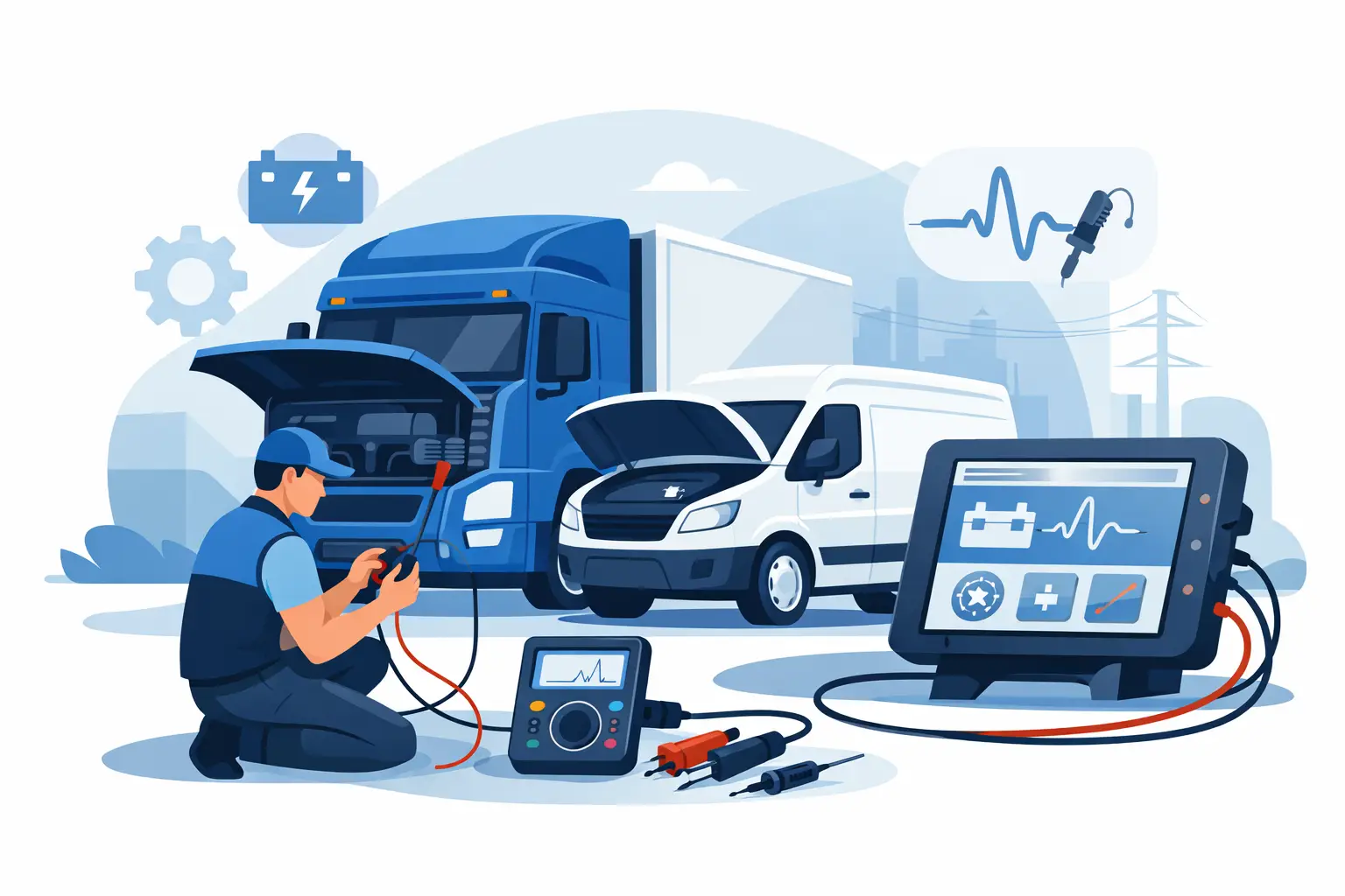
A lorry arrives with an intermittent warning lamp, a no-start complaint or an AdBlue fault that appears only under load. Replacing the component named by a diagnostic trouble code may get it moving, but it is often an expensive guess. This commercial vehicle electrical testing guide sets out a workshop method for proving the supply, earth, signal and network conditions before parts are ordered.
On EURO 5 and EURO 6 vehicles, electrical diagnosis is no longer confined to batteries, alternators and lights. Engine management, SCR systems, body control modules, telematics and braking systems share power supplies and CAN networks. A poor earth point or voltage drop at a fuse carrier can therefore create several unrelated-looking faults. Test the circuit in service, record the result and only then decide whether a repair, wiring repair or control-unit investigation is justified.
Start with the complaint, not the fault code
Ask when the fault occurs. Does the vehicle fail to start after standing overnight, lose power only when hot, or show warnings when auxiliary equipment is operating? A clear driver report helps separate a permanent circuit failure from a vibration, heat or load-related issue.
Carry out a visual inspection before connecting test equipment. Check battery terminals, chassis earth straps, fuse boxes, relay sockets, wiring around the starter and alternator, and harness sections exposed to exhaust heat, road spray or cab movement. On tractor units, pay particular attention to connectors near the chassis, battery box and rear-of-engine area. Green deposits in a connector, a stretched harness or a poorly fitted previous repair can explain a fault more quickly than an hour of scan-tool work.
Then perform a full vehicle scan and save the report. Record active and stored codes, freeze-frame data, system voltage and module communication status. Clear nothing until the initial condition has been captured. A code identifies what a control unit has detected, not necessarily the part that has failed. For example, an SCR pressure or temperature code may be caused by a damaged wire, a weak reference supply, connector corrosion or a genuine sensor fault.
Build a reliable electrical baseline
Electrical testing begins at the batteries. A battery can show an acceptable open-circuit voltage yet collapse during cranking. Test state of charge, conductance where suitable and terminal condition, then assess voltage under load. For a 24 V lorry system, pay attention to the balance between the two 12 V batteries as well as total system voltage. One weak battery can create uneven charging and erratic electronic behaviour.
Next, check the charging system with electrical consumers operating. Measure at the alternator output and again at the battery terminals. A meaningful difference points to resistance in the positive cable, isolation switch, fuse link or connection. Do the same on the earth side. Never assume a shiny-looking cable is electrically sound internally.
Voltage-drop testing is usually more useful than a simple continuity check. Continuity can look perfect with no current flowing, while a corroded joint fails as soon as the starter, heater blower or dosing system draws load. Place the meter across the cable or connection being tested and operate the relevant circuit. The reading shows how much voltage is being lost through that section. Compare both sides of the circuit and investigate unusual differences rather than relying on one universal pass figure.
A basic test set should include a quality digital multimeter, current clamp, back-probing leads, fused test leads and a suitable diagnostic interface. An oscilloscope becomes valuable for intermittent sensor signals, injector circuits, alternator ripple and CAN communication. The tool matters, but the test plan matters more. Use manufacturer wiring information and connector views for the exact make, model, engine and production year.
Test power, earth and signal in the right order
Most actuator and sensor circuits can be approached in the same sequence. First confirm the correct feed voltage at the component connector. Then prove the earth under load. After that, assess the control or signal wire. This prevents a common workshop mistake: condemning a sensor because its output is wrong when it has never received a stable supply.
For a five-volt reference circuit, do not measure only at the ECU. Test at the sensor with the circuit connected where possible. A shorted sensor or chafed harness may pull the shared reference down and affect several components. Disconnecting one branch at a time, following the wiring diagram, can isolate the source without replacing multiple sensors.
Where an ECU switches the earth side of an actuator, a test lamp or current clamp can confirm whether the circuit is being commanded. Use appropriately rated equipment and avoid improvised probing. Excessive current or a careless short at a control-unit pin can turn a wiring repair into an ECU replacement.
Connector testing deserves patience. Inspect pin tension, terminal spread, water ingress and evidence of overheating. Back-probe from the rear where safe rather than forcing oversized probes into terminal faces. If a fault changes while the harness is moved, document the exact section and repair it properly with suitable wire, seals and strain relief. Twisting wires together and covering them with tape is not a durable repair on a working commercial vehicle.
CAN faults need a network approach
A CAN communication code does not automatically mean a failed control unit. Low battery voltage, poor module power or earth, water in a connector and incorrect aftermarket wiring can all interrupt communication. Start by checking whether the affected module is powered and earthed, then determine whether the diagnostic tool can communicate with other modules on the same network.
With the vehicle powered down and the network allowed to sleep, resistance checks between CAN high and CAN low can provide an initial indication of termination condition. However, this test alone cannot prove network health. A scope is the better tool when the fault is intermittent or when modules wake and drop off the network. Look for a balanced signal, noise, reflections and abnormal voltage levels while recreating the reported condition.
Avoid disconnecting modules at random on a live network. Follow the manufacturer procedure, isolate power when required and protect settings that may be lost during battery disconnection. On vehicles with bodybuilders’ equipment, inspect added wiring carefully. Incorrect connections to ignition feeds, earths or data lines regularly create faults that appear to be original vehicle issues.
Diagnose SCR and emissions circuits without guesswork
SCR-related faults can affect torque availability, starting permissions and operating costs, so the pressure to find a fast answer is understandable. The correct answer is still a measured diagnosis. Check supply voltage, grounds, fuse protection, heater circuits, pump current draw, sensor references and harness routing before replacing dosing components.
Live data should agree with physical conditions. If an exhaust temperature sensor reports an implausible value on a cold vehicle, compare it with ambient temperature and test the sensor circuit. If NOx readings are implausible, inspect the connector and wiring near high-temperature exhaust sections before condemning the sensor. A wiring fault may be visible only after heat has softened the harness or vibration has moved it against a bracket.
Any repair to emissions-related equipment should retain the vehicle’s approved emissions controls and comply with applicable roadworthiness and type-approval requirements. Diagnostic equipment is there to identify the root cause, confirm a repair and return the lorry to correct operation – not to mask a fault that will return under load.
Verify the repair under operating conditions
A successful repair is more than a warning lamp that stays off in the workshop. Clear codes only after the defect has been corrected, then repeat the test that caused the complaint. This may mean a cold start, extended crank, electrical load test, road test, regeneration-related checks or a harness movement test.
Check live data and rescan every relevant control unit afterwards. Confirm charging voltage, fault status and communication stability. If connectors were disturbed, inspect locking tabs and harness retention one final time. A repair that survives a road test but fails after the first washdown or rough delivery route is not finished work.
Record meter readings, scope captures, fault codes, repairs made and replacement part numbers on the job card. This protects the workshop, supports warranty decisions and gives the next technician a usable history. It also reveals repeat patterns across a fleet, such as water entry at a known connector or cable damage on a particular chassis layout.
When to escalate the diagnosis
Some cases need model-specific wiring data, specialist programming equipment or ECU-level investigation. Escalate when feeds and earths are proven, wiring integrity has been checked under load, the network signal is abnormal, or a programmed replacement module is required. Guessing at this stage is costly, particularly on DAF, MAN, Iveco, Mercedes-Benz, Scania, Renault and Volvo platforms where variant, engine and software differences matter.
A disciplined electrical process saves more time than it adds. Prove the basics, test the circuit under the conditions that create the fault and use diagnostic data as evidence rather than a parts list. That approach keeps bays moving, reduces repeat repairs and gives fleet customers the dependable result they expect.
