Have Additional Questions? Contact Us →

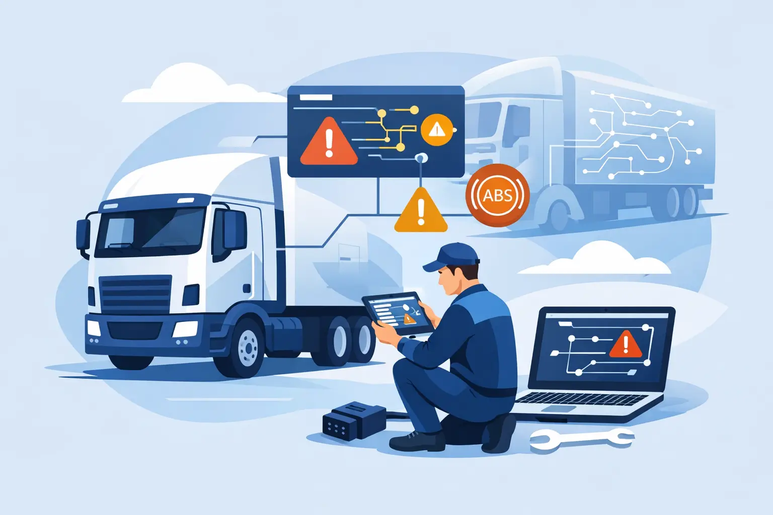
A lorry can arrive with a dashboard full of unrelated warnings: ABS unavailable, gearbox communication lost, AdBlue system fault, retarder inactive and engine derate messages. That pattern is often more useful than any individual fault code. To identify lorry CAN faults efficiently, treat it as a network problem first, not a list of failed components.
On EURO 5 and EURO 6 commercial vehicles, CAN communication links engine management, transmission, braking, body control, instrument cluster, SCR/AdBlue equipment and diagnostic sockets. A single damaged pair of wires, weak ECU supply or failed termination point can remove several control units from the network. Replacing sensors before proving the network condition wastes workshop time and can leave the vehicle off the road longer than necessary.
Start by reading the fault pattern
Use a suitable heavy-duty diagnostic tool and carry out a complete vehicle scan before disconnecting anything. Record all stored, pending and active codes, then note which ECUs respond and which do not. A communication code in one module does not automatically mean that module has failed. It may simply be reporting that another controller has disappeared from the CAN line.
Look for common wording such as “no communication”, “CAN message missing”, “timeout”, “invalid data received” or “control unit not responding”. If multiple systems report a missing message from the same ECU, concentrate on that ECU’s power, ground, connector condition and CAN branch before condemning the wider network.
The timing matters too. A fault present only during cranking may indicate low battery voltage or a poor main earth. A fault that appears after rain, bodywork repairs or trailer connection points towards moisture ingress, harness damage or a disturbed connector. An intermittent issue on rough roads often means a wire break inside insulation, a loose terminal or a connector that has lost pin tension.
Understand which CAN network you are testing
Modern lorries commonly use more than one communication network. High-speed CAN usually carries powertrain, brake and chassis traffic. A separate body CAN may serve lighting, cab systems and convenience functions. Some vehicles also use LIN, FlexRay or Ethernet-derived systems for specific equipment.
This distinction prevents a basic but expensive mistake: testing the wrong pair of wires. Refer to the correct manufacturer wiring diagram for the exact make, model, model year, engine and ECU configuration. A DAF LF, Scania R-series, Mercedes-Benz Actros, MAN TGX, Volvo FH, Renault Trucks range or Iveco platform can each have different network architecture, connector locations and splice points.
Do not assume wire colours are identical across model years or repair sections. Confirm the ECU pins and network designation from the diagram. On some systems, the diagnostic connector gives access to one network only, while the failed section may sit behind a gateway module.
Identify lorry CAN faults with basic electrical checks
Before measuring CAN resistance or waveform quality, check the vehicle’s electrical foundation. Low supply voltage creates misleading communication codes and can make a healthy network appear unstable.
With a multimeter, check battery condition, charging voltage where appropriate, ECU ignition supply, permanent supply and ground voltage drop under load. A ground can look acceptable when measured with no load but fail when a heater, pump, actuator or ECU wakes up. Check both sides of the circuit rather than relying only on continuity.
Then inspect the physical route. Pay close attention to harness runs near batteries, chassis rails, gearbox housings, exhaust aftertreatment components, cab tilt points and areas exposed to road spray. Look for crushed conduit, chafing, previous repair joints, green corrosion, loose earth studs and water trapped in multi-pin connectors.
A visual inspection is not optional on SCR-equipped vehicles. Heat, vibration and contamination around NOx sensors, dosing modules, supply modules and aftertreatment looms can affect both component operation and communication. However, keep the diagnosis disciplined: an SCR fault code may be a genuine emissions-system fault, a local wiring fault or a network-message issue. The stored description and live data need to support the repair direction.
Check termination resistance correctly
A conventional high-speed CAN network normally has two 120-ohm terminating resistors, one at each end of the bus. With the ignition off, control units allowed to power down and the circuit isolated as specified by the manufacturer, a resistance measurement across CAN High and CAN Low often reads approximately 60 ohms.
A reading close to 60 ohms suggests both terminating resistors are present, but it does not prove the wiring is perfect. Around 120 ohms may indicate one missing termination resistor, an open circuit to one end of the bus or a disconnected ECU that contains termination. A very low reading can point to an additional termination resistor, water contamination, damaged wiring or an incorrect connection.
The exact procedure depends on the vehicle architecture. Some ECUs remain awake for a period after key-off, and some networks use gateway arrangements that change the expected measurement point. Never force a resistance test on a live circuit, and do not use a test lamp on CAN wiring.
Check for shorts and damaged branches
With the network safely powered down and connectors disconnected only where the wiring information allows, test CAN High and CAN Low for unwanted continuity to battery positive, ground and each other. A short may be permanent, but many faults appear only when a harness is flexed, the cab is tilted or a connector is loaded into position.
If the network returns after unplugging one ECU or branch, do not immediately blame that module. Inspect the related harness and connector first. A corroded connector or shorted branch can pull down the entire bus and make a good ECU appear guilty. Reconnect sections methodically, one at a time, while watching communication status on the diagnostic tool.
Use an oscilloscope when the fault is intermittent
A multimeter is useful for supplies, grounds and static resistance. It cannot show the quality of live CAN traffic. For intermittent communication faults, an oscilloscope is the practical next step.
A healthy high-speed CAN signal generally shows opposing activity on CAN High and CAN Low around a common voltage level. The exact waveform varies by vehicle and network loading, so compare it with known-good information where available. What matters is whether both lines switch cleanly, remain complementary and return to a stable recessive state.
Poor termination can produce reflections and ringing. Corrosion, poor joints and excessive resistance can distort the signal. A short to ground or supply can hold one line at an incorrect voltage. An oscilloscope also helps distinguish a dead network from a network that is active but not reaching a particular ECU because of an open branch.
Back-probe carefully with suitable probes and avoid spreading terminals. On high-value commercial vehicle looms, careless probing can create the intermittent fault you were asked to repair.
Separate CAN faults from ECU and component faults
A network code is not always a network failure. If every ECU communicates except one, and CAN signal plus power and ground are correct at that ECU connector, then the module itself becomes a credible suspect. Confirm software level, water damage, connector pin condition and any manufacturer test procedure before replacement or programming.
Likewise, if communication is stable but live data identifies implausible NOx readings, dosing pressure problems or temperature-sensor faults, continue with component-level testing. Do not use a CAN diagnosis to explain away a genuine SCR system defect. Correct repair requires the vehicle’s emissions controls and diagnostic monitoring to remain functional.
After any wiring repair, clear codes, carry out the required ignition cycle and road test under conditions that previously caused the fault. Re-scan every ECU afterwards. A repaired communication line may restore several modules, but one remaining local fault can still be stored and needs its own diagnosis.
Build a repeatable workshop process
The fastest technicians are not the ones who replace parts first. They record the scan, verify power and grounds, confirm the correct network, test resistance and wiring, then use waveform testing where the evidence demands it. That order reduces unnecessary ECU replacement and gives the workshop a repair trail it can stand behind.
For mixed fleets, vehicle-specific diagnostic equipment and accurate wiring data are worth more than generic code readers. Truckdiag supports workshops working on specialist commercial vehicle electronics with tools and equipment selected around real compatibility requirements.
When several warning lamps appear together, resist the pressure to chase each one separately. Prove the communication backbone first, repair only what the test results justify, and return the lorry to service with a fault record that makes the next diagnosis quicker.
