Have Additional Questions? Contact Us →

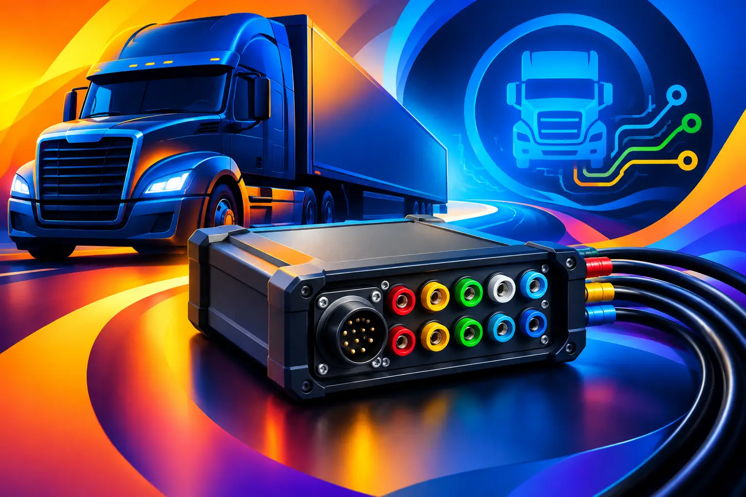
A lorry can show a CAN communication fault while the diagnostic tool reports only a vague inactive code. That is where the top J1939 breakout boxes earn their place on the bench. By giving direct, controlled access to the diagnostic connector pins, they help technicians establish whether the issue is in the vehicle network, the diagnostic lead, an added body system or the test equipment itself.
For a commercial workshop, this is not a gadget purchase. A poor-quality breakout box can introduce loose connections, unclear pin labelling or even an unwanted interruption to a live network. The right unit saves time on electrical fault-finding and gives a technician a safer starting point for voltage, ground and CAN signal checks.
What a J1939 breakout box should do
A J1939 breakout box sits between the vehicle’s diagnostic socket and a diagnostic interface. The vehicle remains connected to the tester through a pass-through lead, while individual circuits are exposed through labelled terminals, sockets or test points. This makes it possible to measure supply voltage, check chassis ground, inspect CAN High and CAN Low, and identify activity on auxiliary communication lines without forcing probes into the vehicle socket.
On heavy-duty vehicles, the main value is isolation of the fault. If a diagnostic tool cannot communicate, the breakout box lets the technician work methodically: confirm that the connector has power and ground, inspect network resistance with the ignition off where appropriate, then assess CAN signals using a suitable multimeter or oscilloscope. It narrows the question from “why will the tool not connect?” to a circuit-level fault that can be traced.
A breakout box does not replace OEM diagnostic software, a quality interface or a wiring diagram. It complements them. The box provides access; the wiring information explains what should be present at each pin; the diagnostic platform identifies the affected control unit and fault context.
Top J1939 breakout boxes: the designs worth buying
There is no single best option for every fleet or workshop. The right choice depends on the age of the vehicles being serviced, the diagnostic interfaces in use and whether the work is limited to basic connection faults or includes regular CAN network investigation.
1. A basic 9-pin pass-through breakout box
For a workshop handling occasional communication faults, a straightforward 9-pin Deutsch-style pass-through box is often the sensible starting point. It should provide clear access to power, ground, CAN High and CAN Low, with a male and female connector arrangement that maintains the connection between vehicle and diagnostic tool.
This type works well for confirming fundamentals: battery supply at the diagnostic socket, voltage drop on ground, continuity checks after isolating the circuit and the presence of network voltage. Choose a model with durable moulded connectors and permanently marked pin positions. Printed labels that disappear after a few months of workshop use are a false economy.
The limitation is that basic boxes may not support additional channels or provide convenient facilities for advanced scope work. They are ideal for quick verification, but less suited to complex multi-network lorries.
2. A colour-coded terminal breakout box
A colour-coded model is a better daily-workshop choice where several technicians use the same equipment. Clearly separated terminals reduce mistakes when moving between meter leads, back-probing adaptors and scope channels. Good labelling also makes training easier and reduces the chance of confusing supply voltage with a communication line.
Look for recessed or shrouded terminals where possible. Commercial vehicle electrical systems can be exposed to dirt, vibration and rushed repairs, so the layout should minimise accidental short circuits. A fused supply test point can also be useful, but it should never be treated as permission to bypass a vehicle circuit’s intended protection.
These boxes are particularly useful for independent repairers dealing with mixed makes. DAF, MAN, Iveco, Mercedes-Benz, Scania, Renault and Volvo vehicles may all arrive with different symptoms, but the first checks at the diagnostic port follow the same disciplined process.
3. A dual-protocol or Type 1 and Type 2 compatible box
Connector compatibility matters more than many buyers expect. Older heavy vehicles commonly use the black 9-pin J1939 Type 1 connector, while later applications may use the green Type 2 arrangement. The physical connector may look familiar, but protocol capability and pin use can differ.
A dual-compatible breakout solution makes sense for mixed fleets, mobile diagnostic work and tool resellers supporting varied vehicle ages. It avoids carrying several improvised adaptors and provides a more controlled connection path. Before ordering, confirm both sides of the box: vehicle-side compatibility and diagnostic-tool-side compatibility.
Do not assume that a green connector alone guarantees compatibility with every interface or application. Check the vehicle build year, connector standard, communication requirements and interface specification. A quality adaptor may be required, particularly where newer high-speed networks are involved.
4. An advanced CAN test box with switchable line access
For electronics specialists and workshops regularly diagnosing intermittent network issues, an advanced CAN breakout box offers more than exposed pins. Useful features can include individual line isolation, integrated test sockets, status LEDs and convenient oscilloscope connection points.
This format is valuable when investigating a network pulled down by a faulty ECU, damaged harness section, aftermarket installation or water ingress. Controlled line access can help a technician divide the circuit and observe the effect, rather than disconnecting random modules and creating new fault memories.
The trade-off is cost and the need for stronger diagnostic discipline. Switches must be used only with a clear understanding of the circuit and test procedure. On a live CAN network, incorrect interruption can stop communication between control units and create misleading results. The box should support diagnosis, not encourage trial-and-error testing.
Check these details before ordering
The connector is the first check, but not the only one. A practical buying decision should consider the full diagnostic setup. Confirm the box is designed for the 9-pin arrangement used on the vehicles you service and that it passes through correctly to your existing diagnostic interface.
Build quality matters. The enclosure should tolerate workshop use, the cable strain relief should be secure and the connectors should engage firmly without excessive movement. A loose diagnostic connection can imitate an intermittent vehicle fault, wasting time and creating avoidable doubt.
Pin identification should be unambiguous. At minimum, technicians need to identify battery positive, ground, CAN High and CAN Low quickly. Where the box exposes additional pins, markings should correspond to a supplied circuit reference. Avoid unlabelled test boards or cheap adaptors that rely on guesswork.
Also consider how the unit will be used. A fixed workshop may benefit from a larger terminal layout that is easy to connect to a scope. A roadside technician may prefer a compact enclosed box with protected sockets and a short, durable lead. Neither approach is automatically better.
A sensible J1939 diagnostic routine
A breakout box produces useful results only when used in sequence. Start by recording the complaint and scanning all available control units before disturbing the network. A single missing ECU may point to a local power or ground problem, while multiple unavailable modules suggest a shared communication or supply issue.
With the correct wiring information available, inspect the diagnostic port and breakout connections for corrosion, bent terminals, moisture and previous repair damage. Then verify power and ground under load where possible. A ground that looks acceptable with no load can still fail when the diagnostic interface draws current.
For CAN checks, follow the vehicle manufacturer’s procedure. Resistance testing should normally be completed with the network powered down and the correct modules connected, while waveform testing requires suitable live-circuit equipment and interpretation. A multimeter can reveal a gross fault, but it cannot show reflections, noise or intermittent distortion in the way an oscilloscope can.
Be cautious around added accessories. Telematics equipment, bodybuilder circuits, tracker installations and non-standard diagnostic adaptors can all affect network behaviour. If the fault began after an installation, inspect that work before condemning an ECU.
When a breakout box is the wrong tool
A breakout box is not the answer to every emissions or engine-management complaint. If communication is stable and the diagnostic system identifies a specific sensor plausibility, SCR dosing, NOx or exhaust-temperature fault, the next step is usually guided testing against the manufacturer procedure, not repeated checks at the diagnostic socket.
Likewise, do not use a breakout box to defeat safety, emissions or security functions. Its role is accurate diagnosis and electrical verification. Proper repair protects vehicle reliability, helps preserve fault records and prevents a temporary workaround becoming a larger fleet problem.
For workshops building a dependable diagnostic bench, a properly specified J1939 breakout box is a small purchase with a direct effect on fault-finding speed. Select it around the connectors and vehicles actually entering your bay, keep a wiring reference beside it, and use it to prove the circuit before replacing parts.
